Main Menu
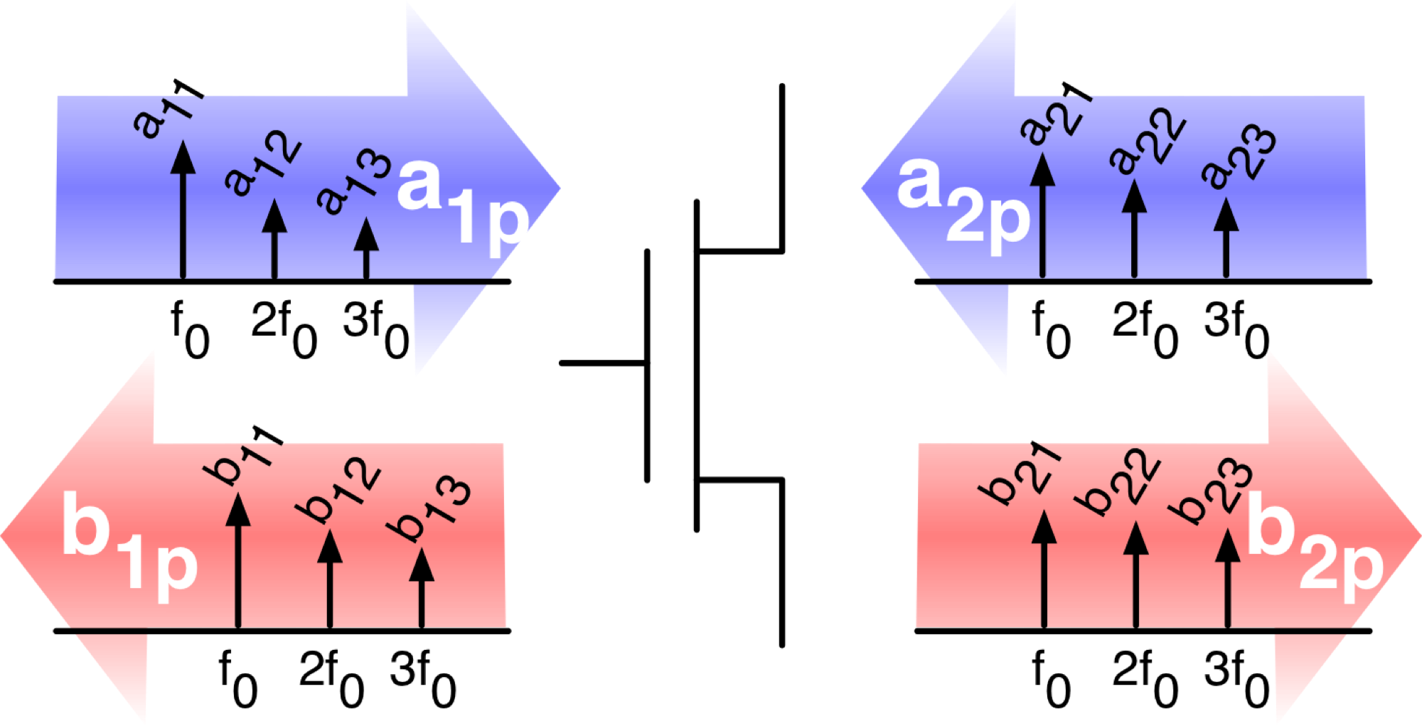
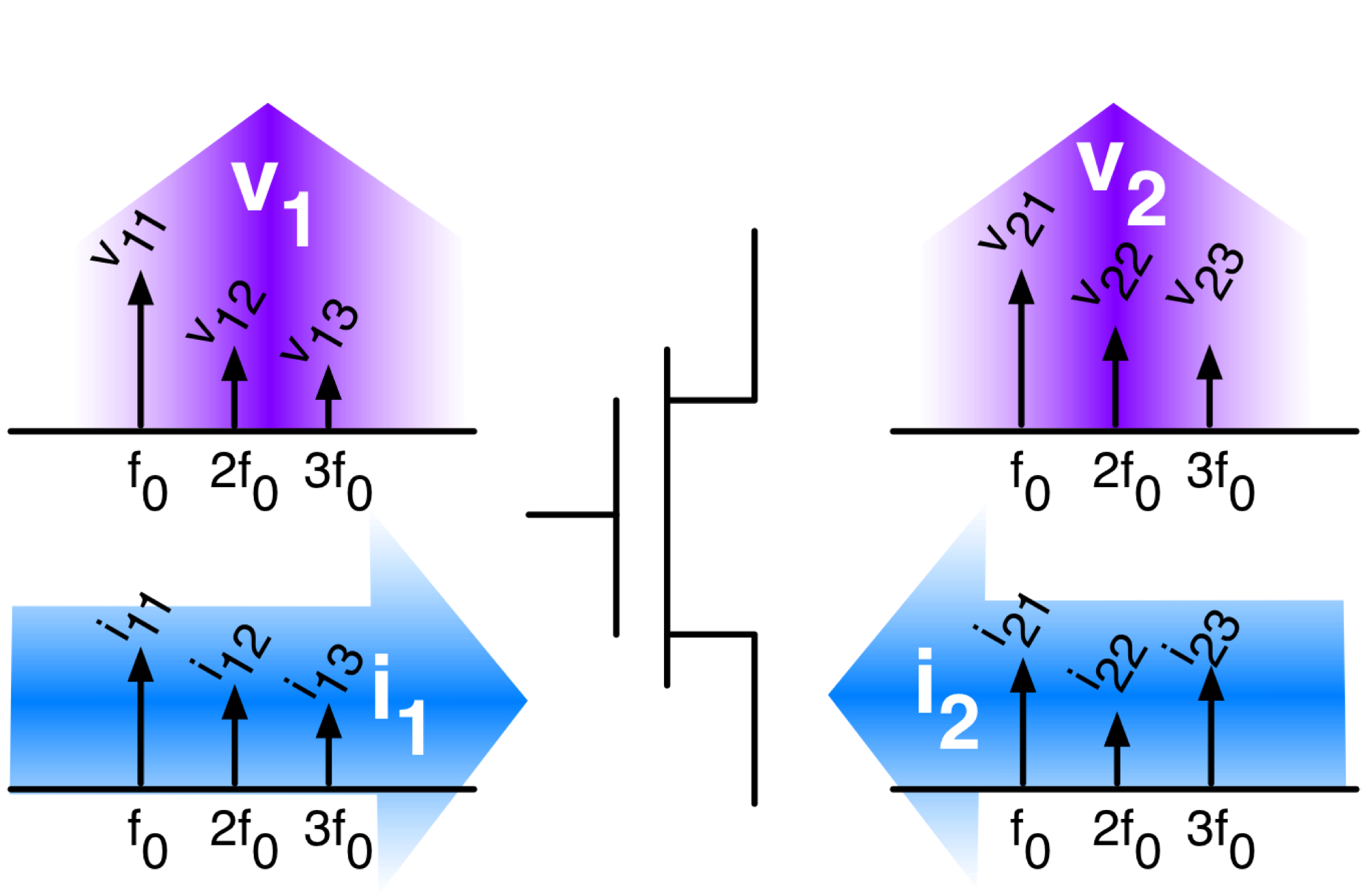
Assuming all devices are connected, a two-port system is modeled as follows:

A 2-Port System with Unknown DUT.
The Main Menu summarizes the test-bench as shown below:
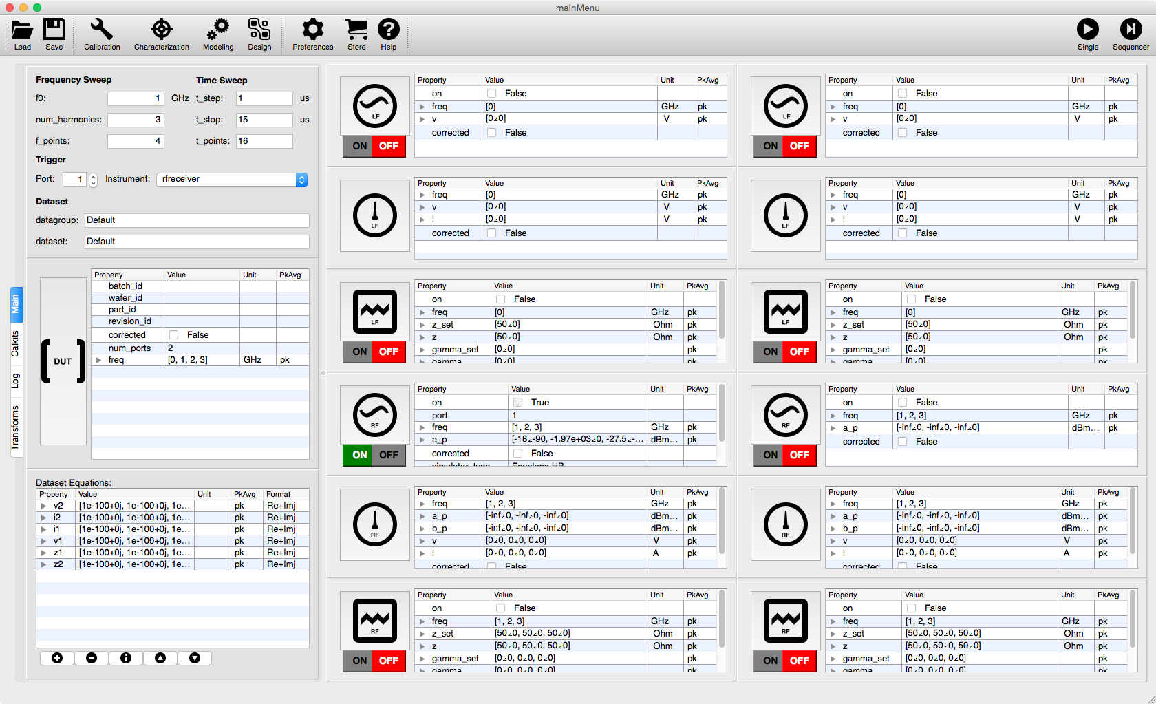
The 2-port System Dashboard Representation
The Main Menu consists of two-primary elements:
The Sidebar
The Instrument Manager
Sidebar
The Sidebar is a multi-tab window that can be customized based on the desired application. The Main Menu defaults to the Main tab.
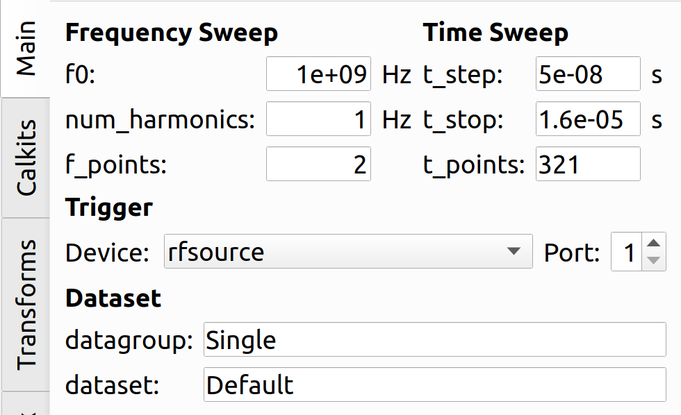
Start by configuring the global System Settings in the sidebar by specifying:
- Frequency Sweep
Settings().f_0: The fundamental carrier frequency.
Settings().num_harmonics: The number of harmonics frequencies.
- Time Sweep
Settings().t_{stop}: the measurement period.
Settings().t_{step}: the measurement time-step.
- Trigger
Settings().trigger_device: the trigger output device type.
Settings().trigger_port: the trigger output device port.
- Datagroup
Settings().datagroup: The name of the database file (default Single.h5).
Settings().trigger_port: The name of a node in a database file (default Default).
You can specify additional global variables:
In the
sknrf.ymlconfig file before runtime.In the Settings Menu during runtime.
Instrument Manager
The Instrument Manager consists of:
Settings().num_ports + 1ports
Port 0 is a reserved calibration reference port.
Settings().num_dutsDUTs
- The aux devices consisting of non-compatible instruments:
Power Meter
Spectrum Analyzer
Vector Network Analyzer
Ports
The number of ports is configured in sknrf.yml and is available at runtime in Settings().num_ports.
Each measurement port is represented by a column in the Instrument Manager.
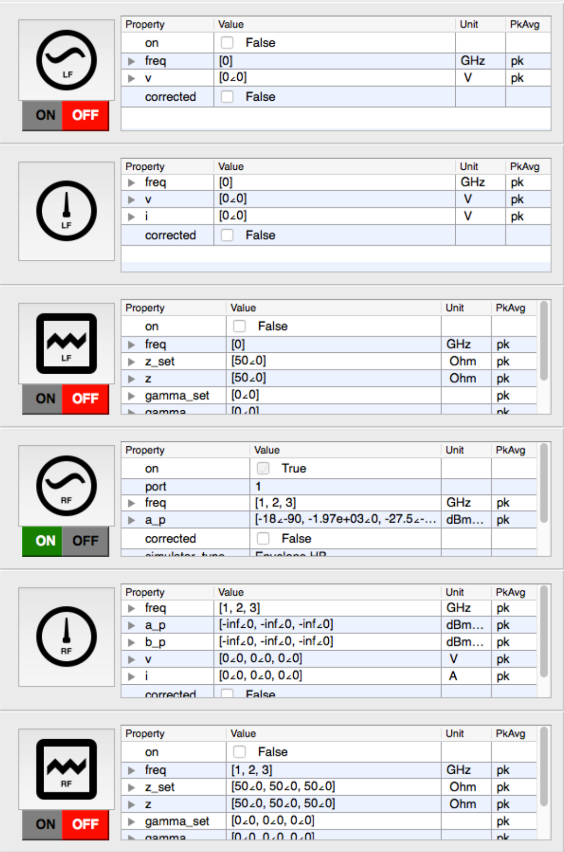
A Port PortModel a collection of devices that can be connected to a
measurement port:
port.lfsource, a low-frequency signal source that sets \(v(t, f)\).
port.lfreceiver, a low-frequency signal receiver that gets \(v(t, f)\) and \(i(t, f)\).
port.lfztuner, a low-frequency impedance controller that sets and gets \(z_p(t, f)\)
port.rfsource, a high-frequency signal source that sets \(a_p(t, f)\).
port.rfreceiver, a high-frequency signal receiver that gets \(a_p(t, f)\) and \(b_p(t, f)\).
port.rfztuner, a high-frequency impedance controller that sets and gets \(\gamma_p(t, f)\).
Each measurement port provides a Thevenin Equivalent at Low-Frequency (LF) and High-Frequency (HF). Thus the following equations fully describe the inputs and outputs of a port:
VIZ->BAG
BAG->VIZ
These raw waveforms have the following meaning:
\(v(t, f)\): The input voltage (default \(0.0\)).
\(i(t, f)\): The output current (default \(0.0\)).
\(z(t, f)\): The port termination impedance (default \(z_0 = 50.0\))
\(b_p(t, f)\): The output (reflected) power-wave (default \(0.0\)).
\(a_p(t, f)\): The input (incident) power-wave (default \(0.0\)).
\(\gamma_p(t, f)\): The port reflection coefficient (default \(0.0\)).
Since each of these waveforms has a default value, we need only connect an instrument when we know that the DUT does not meet these assumptions:
Devices with direct access to power and ground do not require a
port.lfztuner.Devices matched to 50 Ohm do not require a
port.rfztuner.Devices matched to 50 Ohm do not require a
port.rfreceiverthat can measure \(a_p(t, f)\).LF circuits do not require
port.rfsource,port.rfreceiver,port.rfztuner.RF circuits do not require
port.lfsource,port.lfreceiver,port.lfztuner.


